Minimal PDF Drawing Encoder
2021/03/05
PDF is one of those monstrous formats that allow you to do just about anything. Though this can make writing a fully compliant PDF viewer a daunting task, there's nothing that can stop us from putting together a couple of lines of code to make a bare minimum PDF writer for drawing some simple shapes. In fact, it is not unlike writing an SVG by concatenating some strings and numbers with a boilerplate.
Tl;dr
The JavaScript implementation for writing a set of polylines to PDF (useful for plotters):
function polylines2pdf(polylines, colors, width, height) {
  var head = `%PDF-1.1\n%%¥±ë\n1 0 obj\n<< /Type /Catalog\n/Pages 2 0 R\n>>endobj
    2 0 obj\n<< /Type /Pages\n/Kids [3 0 R]\n/Count 1\n/MediaBox [0 0 ${width} ${height}]\n>>\nendobj
    3 0 obj\n<< /Type /Page\n/Parent 2 0 R\n/Resources\n<< /Font\n<< /F1\n<< /Type /Font
    /Subtype /Type1\n/BaseFont /Times-Roman\n>>\n>>\n>>\n/Contents [`;
  var pdf = "";
  var count = 4;
  for (var i = 0; i < polylines.length; i++) {
    var r = (((colors[i]>>16)&0xFF)/255).toFixed(2);
    var g = (((colors[i]>>8)&0xFF)/255).toFixed(2);
    var b = ((colors[i]&0xFF)/255).toFixed(2);
    pdf += `${count} 0 obj \n<< /Length 0 >>\n stream \n /DeviceRGB CS \n${r} ${g} ${b} SC\n`;
    for (var j = 0; j < polylines[i].length; j++){
      var [x,y] = polylines[i][j];
      pdf += `${x} ${height-y} ${j?'l':'m'} `;
    }
    pdf += "\nS\nendstream\nendobj\n";
    head += `${count} 0 R `;
    count ++;
  }
  head += "]\n>>\nendobj\n";
  pdf += "\ntrailer\n<< /Root 1 0 R \n /Size 0\n >>startxref\n\n%%EOF\n";
  return head+pdf;
}
Yup! just 20 lines. Usage (assuming node.js):
var polylines = [
  [[100,100],[200,100],[200,200],[100,200],[100,100]],
  [[300,200],[50,400],[400,300],[300,200]],
  [[100,100],[400,400]]
]
var colors = [
  0xFF0000,
  0x000000,
  0x0000FF
]
var pdf = polylines2pdf(polylines, colors, 450, 450);
require('fs').writeFileSync("output.pdf",pdf);
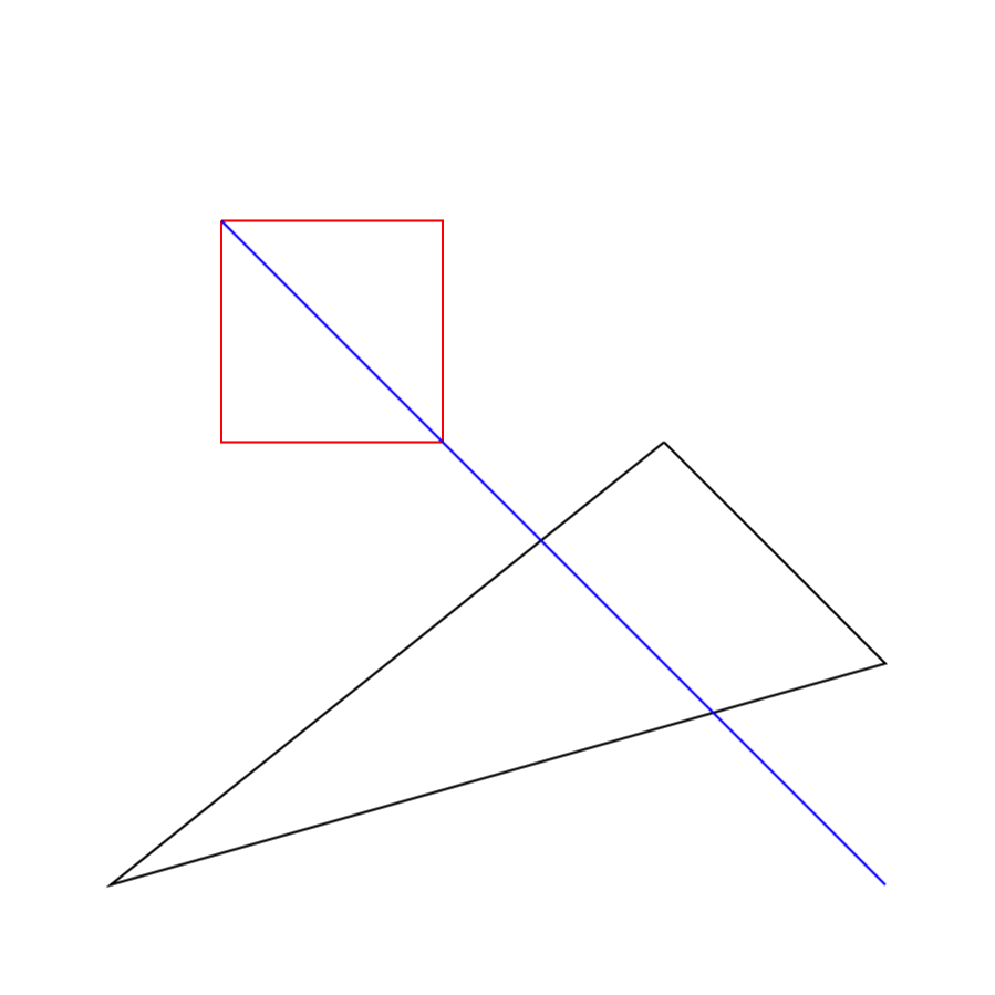
You should be able to see something like this when opening the PDF file in your favourite viewer (tested on Chrome 89, Adobe Acrobat Reader DC 2020, Preview.app/Finder.app):
Explanation
Let's get started by taking a look at this helpful page about writing minimal PDF by hand:
It is easy to spot that the first 30 or so lines are all boilerplate: It defines a “catalog” that contains the “pages” which contains a “page”, and the last one is where we'll append our drawing to. There're really only two places we're interested in here:
- First is the
MediaBox. It apparently defines the dimensions of the drawing, which we need to make variable for our writer. - Second is the line
/Contents 4 0 R. It lists the children for the page objects, which we need to keep updated as we add more. For example,/Contents [4 0 R 5 0 R 6 0 R 7 0 R]and so on, with4567being object indices.
%PDF-1.1
%¥±ë

1 0 obj
  << /Type /Catalog
     /Pages 2 0 R
  >>
endobj

2 0 obj
  << /Type /Pages
     /Kids [3 0 R]
     /Count 1
     /MediaBox [0 0 300 144]
  >>
endobj

3 0 obj
  <<  /Type /Page
      /Parent 2 0 R
      /Resources
       << /Font
           << /F1
               << /Type /Font
                  /Subtype /Type1
                  /BaseFont /Times-Roman
               >>
           >>
       >>
      /Contents 4 0 R
  >>
endobj
The document then goes on to draw a piece of text, which our writer will substitute with shapes/paths, and finally there's the mysterious xref section, which I find safe to omit, as PDF viewers seem to do just fine without them.
So now the key question is, how to draw shapes? The answer lies in Adobe's PDF Spec. Turn to page 132 and you'll be able to find the following table:
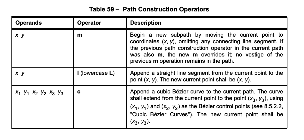
(There're commands for various variations of Bézier curves etc. on the very next page, but let us focus on straight lines right now).
If we're familiar with the syntax of SVG <path> element, we can see that PDF paths are based on very similar ideas. (Otherwise, this MDN tutorial on this type of “command-based” drawing might be a helpful read). Perhaps the most significant difference between PDF and SVG commands is that the commands are postfix in PDF. So to draw a line from (1,2) to (3,4) instead of
M 1 2 L 3 4
found in SVG, in PDF we have this:
1 2 m 3 4 l
But wait, notice the line that says:
Note that the path construction operators do not place any marks on the page; only the painting operators do that.
Glad we spot that, saving a lot of potential head scratching. On page 135, we can find the “painting operators” of which it speaks:
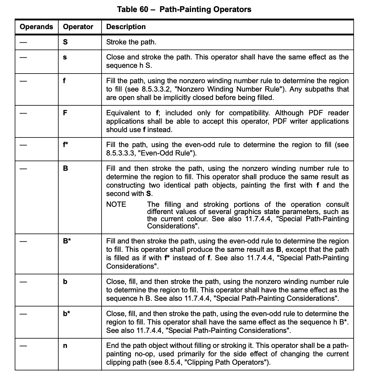
Pretty straightforward. Apparently for linedrawings, S is the guy we need to append to the end of the path.
Cool! Now let's try drawing a single line by modifying the minimal PDF example downloaded from the aforementioned page. You can open the PDF with your favourite text editor (Sublime, VSCode, vim, or what have you) as if it is plain text. In it, find the text drawing code:
4 0 obj
  << /Length 55 >>
stream
  BT
    /F1 18 Tf
    0 0 Td
    (Hello World) Tj
  ET
endstream
endobj
…and replace it with something like this, to draw a Stroke by moving to (100,50) and drawing a line to (200,100):
4 0 obj
  << /Length 26 >>
stream
  100 50 m
  200 100 l
  S
endstream
endobj
Note that the number in << /Length >> seems to be for the count of characters between right after stream and right before endstream. In practice, PDF viewers doesn't seem to pay attention: the JS implementation I showed at the beginning simply put 0s there for all streams.
Press save in the text editor, and opening up the file in a PDF viewer you should be able to see the line we just drew:
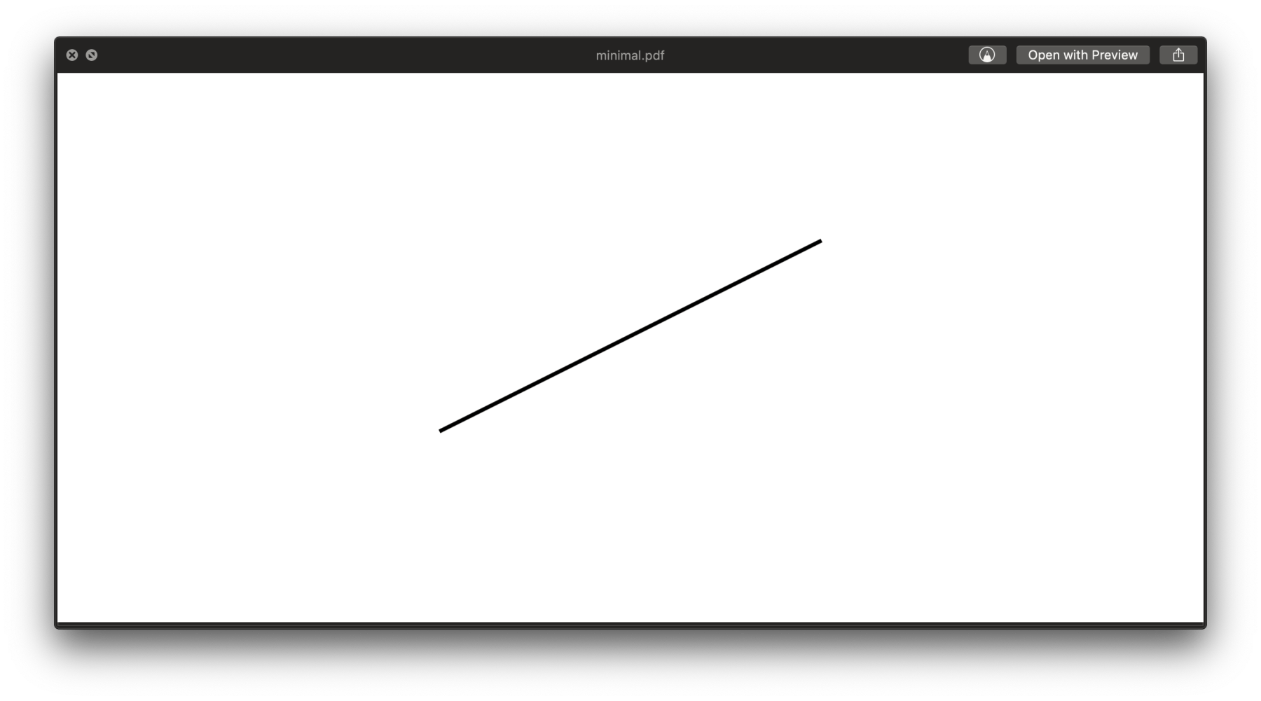
But wait! Didn't we ask for a line from (100,50) to (200,100)? How come it slopes upwards instead of downwards? This is because, unlike what we're used to, PDF's coordinate system put (0,0) on the lower left corner, and y axis points upwards:
  +-----------+
^ |           |
| |           |
+y|           |
  |           |
  |           |
 0+-----------+
  0     +x  ->
OK! Slightly annoying but not a problem. Now we also know how to paint a triangle, from checking the spec (f for “fill”):
4 0 obj
  << /Length 37 >>
stream
  110 50 m
  200 70 l
  150 120 l
  f
endstream
endobj
And yup:
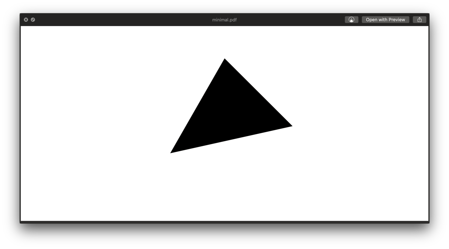
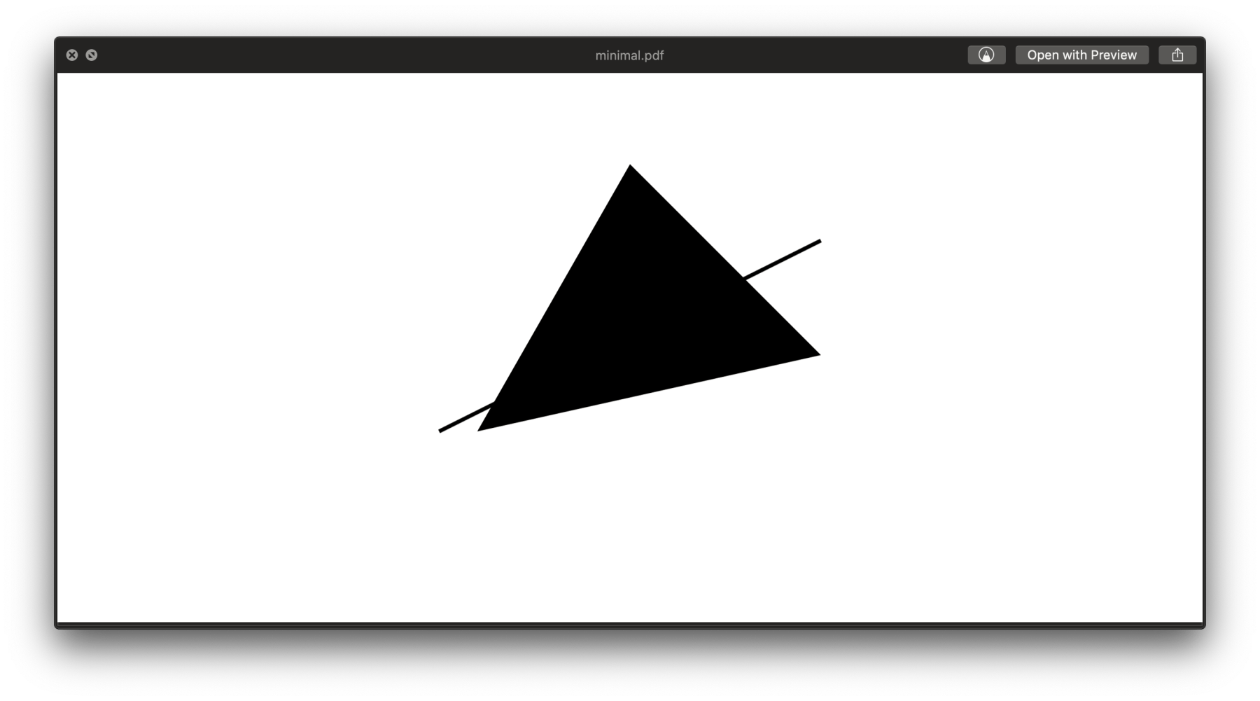
So far we've learned how to draw single objects. For multiple objects, there're two things we need to take care of. First, the object index need to increase for each; second, we need to register the object indices with the page.
So starting from the 3 0 obj line until before xref, we put the following to draw both the line and the triangle we had:
3 0 obj
  <<  /Type /Page
      /Parent 2 0 R
      /Resources
       << /Font
           << /F1
               << /Type /Font
                  /Subtype /Type1
                  /BaseFont /Times-Roman
               >>
           >>
       >>
      /Contents [4 0 R 5 0 R]
  >>
endobj

4 0 obj
  << /Length 37 >>
stream
  110 50 m
  200 70 l
  150 120 l
  f
endstream
endobj

5 0 obj
  << /Length 26 >>
stream
  100 50 m
  200 100 l
  S
endstream
endobj
Notice the index change for the stroke from 4 0 obj to 5 0 obj to avoid clashing with that of the triangle, as well as /Contents [4 0 R 5 0 R] where they're registered with the page.
Our PDF now renders to this:
Time to add some colors!
On page 143 of the spec, we figure out that it has this to say about RGB colors:

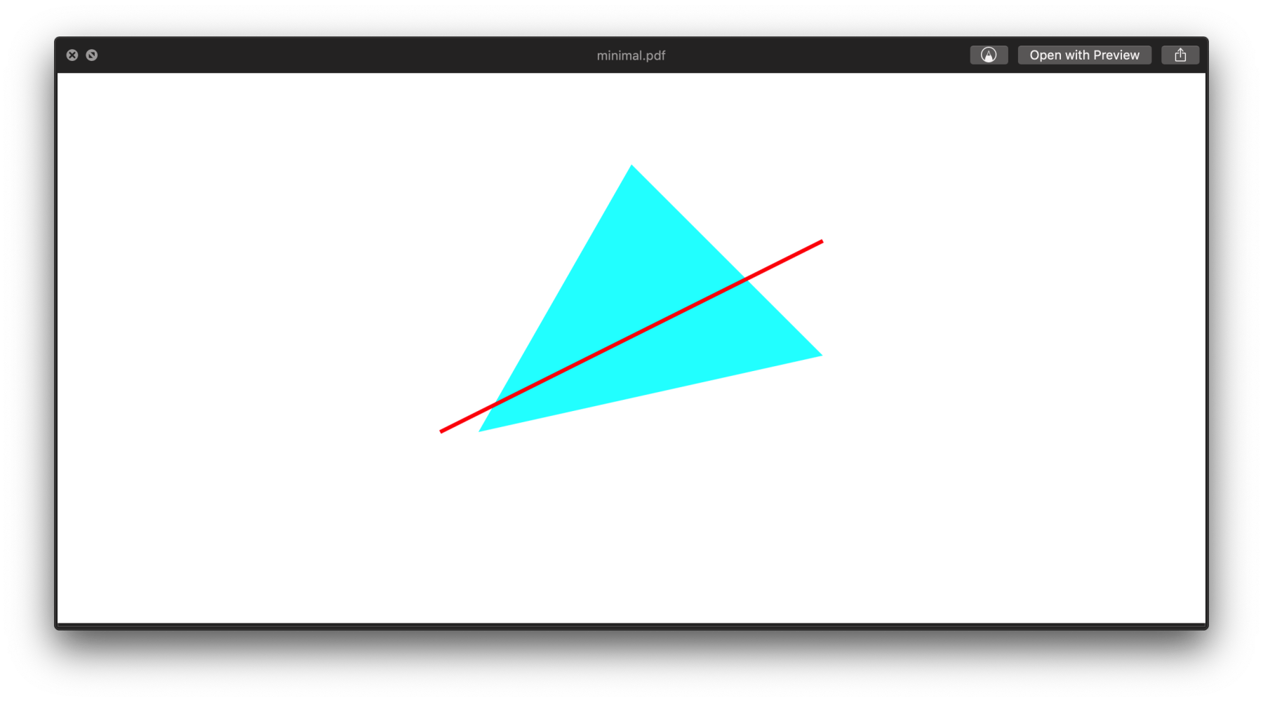
So basically CS begins color space definition, and SC ends it? How quaint and bash-ish. Nevertheless let's try it out, by painting the triangle in cyan and line in red:
4 0 obj
  << /Length 62 >>
stream
  /DeviceRGB cs 0 1 1 sc
  110 50 m
  200 70 l
  150 120 l
  f
endstream
endobj

5 0 obj
  << /Length 51 >>
stream
  /DeviceRGB CS 1 0 0 SC
  100 50 m
  200 100 l
  S
endstream
endobj
Notice how for the filled shape, we're using lowercase cs/sc, and for the stroke, uppercase CS/SC. Also notice that RGB components are specified in the 0.0-1.0 range. Ta-da:
There's one last thing: a useful table for stylizing the stroke on page 127:
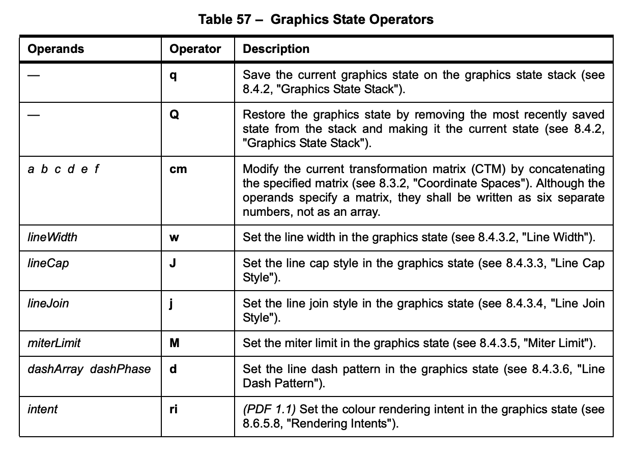
Recall that these are also postfix, so to draw a line of width 10, we need to put 10 w, like so:
5 0 obj
  << /Length 58 >>
stream
  /DeviceRGB CS 1 0 0 SC
  10 w
  100 50 m
  200 100 l
  S
endstream
endobj
Finally let's practice by modifying the polylines2pdf function to polygons2pdf for filled shapes, to consolidate our understanding of the format.
- First we need to change
Stof(obviously) - Recall that we also need to change
CSandSCto lowercase, for filled shapes.
function polygons2pdf(polylines, colors, width, height) {
  var head = `%PDF-1.1\n%%¥±ë\n1 0 obj\n<< /Type /Catalog\n/Pages 2 0 R\n>>endobj
    2 0 obj\n<< /Type /Pages\n/Kids [3 0 R]\n/Count 1\n/MediaBox [0 0 ${width} ${height}]\n>>\nendobj
    3 0 obj\n<< /Type /Page\n/Parent 2 0 R\n/Resources\n<< /Font\n<< /F1\n<< /Type /Font
    /Subtype /Type1\n/BaseFont /Times-Roman\n>>\n>>\n>>\n/Contents [`;
  var pdf = "";
  var count = 4;
  for (var i = 0; i < polylines.length; i++) {
    var r = (((colors[i]>>16)&0xFF)/255).toFixed(2);
    var g = (((colors[i]>>8)&0xFF)/255).toFixed(2);
    var b = ((colors[i]&0xFF)/255).toFixed(2);
    pdf += `${count} 0 obj \n<< /Length 0 >>\n stream \n /DeviceRGB cs \n${r} ${g} ${b} sc\n`;
    for (var j = 0; j < polylines[i].length; j++){
      var [x,y] = polylines[i][j];
      pdf += `${x} ${height-y} ${j?'l':'m'} `;
    }
    pdf += "\nf\nendstream\nendobj\n";
    head += `${count} 0 R `;
    count ++;
  }
  head += "]\n>>\nendobj\n";
  pdf += "\ntrailer\n<< /Root 1 0 R \n /Size 0\n >>startxref\n\n%%EOF\n";
  return head+pdf;
}
A Java version of this minimal encoder is used by the Processing Embroidery library, PEmbroider, where PDF is among its many supported output formats.